


 Technology (Tutorials, Opinions, & More) Technology (Tutorials, Opinions, & More)
 Technology Repair Log Technology Repair Log
Technology Repair Log

Repairing a modern speaker
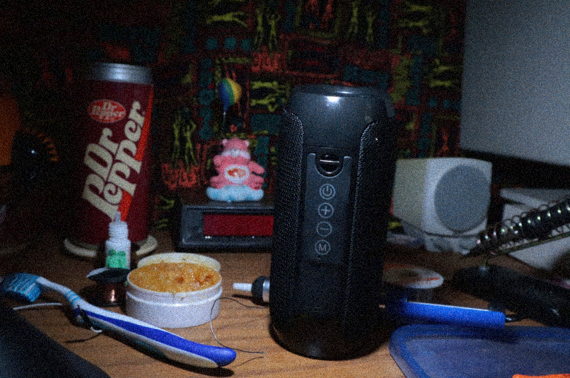
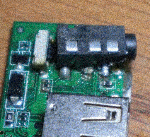
I use this speaker frequently. I never use the bluetooth feature in the speaker. Instead, I use the auxillary input. However, one day I left a 3.5mm jack in the speaker, put it in my dresser, and once I closed the dresser, the jack got caught and snapped off the auxillary input jack from the PCB.
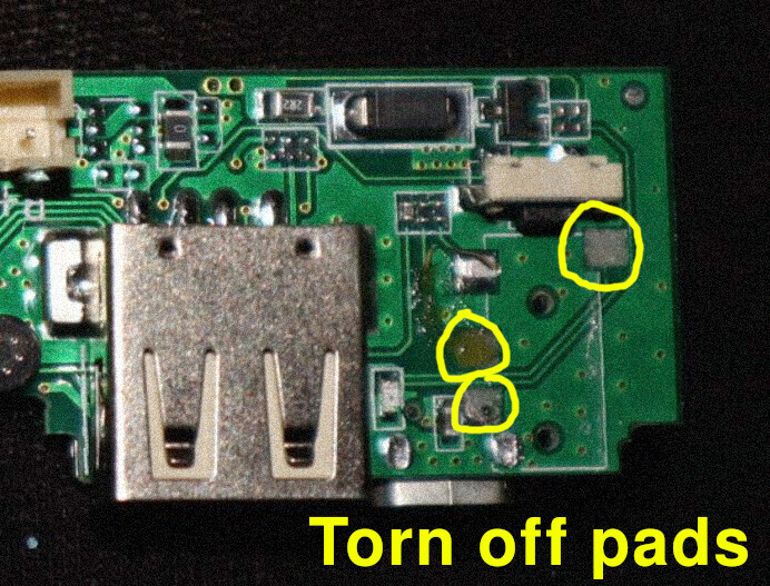
Problem: This was a nightmare because 3 out of the 4 solder pads holding the aux. input to the PCB lifted off the board. When this happens, it's difficult to get the component soldered back to the board and to be stable.
Solution #1: Getting the aux input back on the PCB with stability.
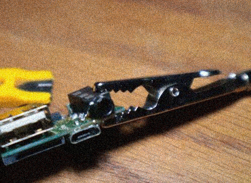
As mentioned, most of the PCB pads were lifted, giving the aux input nothing to hold onto with solder. Since there isn't much solder holding the aux input to the PCB, the aux. input is loose and could snap off again. To solve this, I desoldered the aux input and put super glue on the PCB (where it wasn't obscuring anything) and held the aux input in place with an alligator clip for 15 minutes.
Solution #2: Solder over the removed PCB pads
Even though the PCB pads were completely removed, I was able to get the aux input to stick to the board by flowing a lot of solder from the solder joints to the lifted PCB pad areas. Although probably not ideal, it worked. I needed these solder blobs in order to do a jumper wire and to connect the lifted PCB traces to the solder blobs.
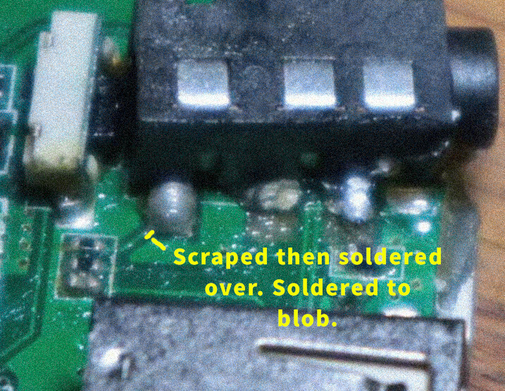
Solution #3: Scrap away to expose more PCB traces
One of the other issues is that 2 PCB traces were removed. If a PCB trace is removed, it will not successfully flow through the power from one component (in my case an SMD ceramic capacitor) to another component (the aux input). You can solve this by scraping a bit of the trace to expose the copper. Once the copper is exposed, lay some flux on it, put some solder on your soldering iron, and run it over the exposed copper. The exposed copper will have solder on it. Depending on how close the solder trace and the following component is, you can make a solder blob and bridge the two together, which is what I did for one of the traces. However, the other lifted trace was too far away from the component it lead to. This is a great time to use a jumper wire.
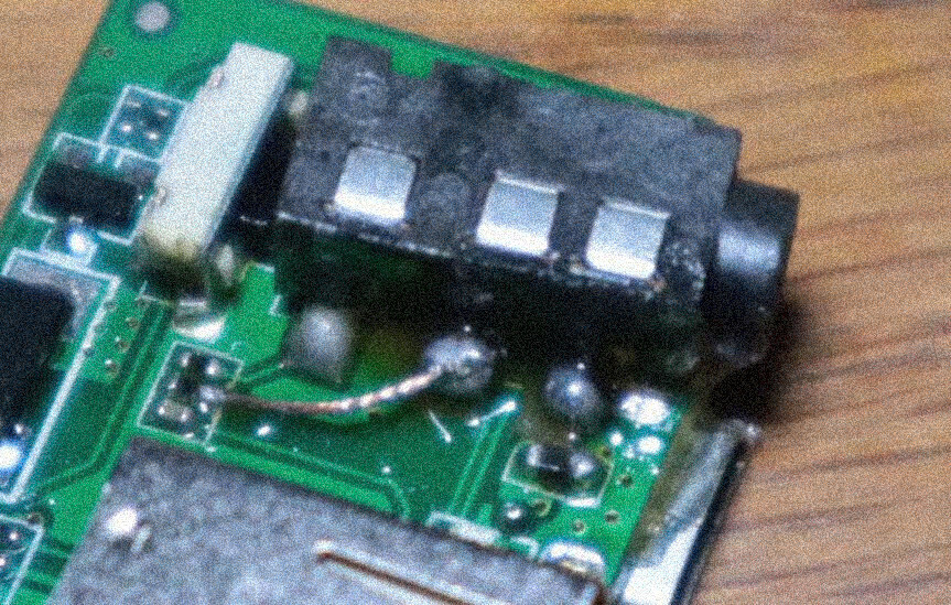
Solution #4: Making a jumper wire
Since one of the traces on the PCB had most of the copper removed, I had no other choice but to bridge the connection with a jumper wire. I removed the casing from the wire, because a case on the wire would be too bulky and force too much pressure, resulting in the wire possibly breaking.
I cut a small piece of wire, then removed the casing. I twisted the edges of the wire so they weren't frayed. I dipped the edges of the wire in flux. Then I put solder onto my iron. Next, I held one end of the wire to the exposed PCB trace (that has solder on it, so it has something to bond to). I applied my iron (with solder on it), to the PCB trace. The trace and wire were successfully soldered together. I repeated a similar process with the other end of the wire, applying the other end of the wire to the PCB component the trace was leading to.
Results:
Everything worked as intended. To make this a little confusing, at fist I did not apply the super glue. I initially did the rest of the process I wrote here sans super glue. When I plugged a 3.5mm jack into the input, then unplugged it, the aux input once again ripped away from the PCB, exposing the same traces and the same PCB pads. This time I super glued the aux input down and repeated everything I wrote here. One error I made is that the super glue initially did cover a component that needed solder on it. I couldn't get the speaker to work until I looked at picture I took of the PCB and realized there was a component that was hidden away. I started scraping off the super glue and saw the empty PCB pad that needed solder flowed to it. Once I did this, it worked again. So I fixed it, broke it, then fixed it again.
Fixability:
Overall, I was surprised that this modern device was really easy to disassemble and to fix. I usually avoid trying to fix modern devices because they don't interest me, and their boards are machine printed, meaning the components are extremely small and hard to work with compared to vintage devices. However, I use this speaker very frequently to listen to music, so I wanted to fix this instead of throwing it away and spending $20 on a new one. Better yet, no spudging tools necessary for this repair. Just phillips head screws (that ended up being stripped. This is why I prefer flatheads.)
Click here to go back to the log of repaired vintage technology.
|

 News
News
 Who am I?
 My Monthly Column